Intermediate Computer Graphics Week 10: Misc Post-Processing Effects

For my last blog entry for this course, I figured I would just give a few miscellaneous post-processing effects, with explanations of how they work and a bit of code. The effects that I will talk about are color correction and hatching.

Color Correction

Color correction is simply the process of substituting certain colors in the scene for other colors. For example, you may want to add a “colorblind mode” to your game, which changes all of the colors so that they are more distinguishable to people who have certain types of colorblindness. Rather than adding new textures for all of the objects in the game for such modes, we can use a color correction shader with the appropriate color ramp to take care of this for us. A color ramp is a 1 by 256 pixel texture that simply indicates how the colors will be mapped. It is usually created in an image editing program by first creating a gradient that goes from black to white. Then, the ‘levels’ feature of the image editing software is used to modify the levels of each color channel. This ramp is used in our shader by first sampling the scene to get the current color, then for each color channel, the color ramp is sampled to obtain the output color.

The code for this effect would look something like this:

#version 420

in vec2 texCoord;

out vec4 color;

uniform sampler2D scene;
uniform sampler1D colorCorrectionMap;

void main()
{
	vec4 source = texture(scene, texCoord);

	color.r = texture(colorCorrectionMap, source.r).r;
	color.g = texture(colorCorrectionMap, source.g).g;
	color.b = texture(colorCorrectionMap, source.b).b;
	color.a = 1.0;
}

Here is an example of what a scene looks like before and after color correction, along with the ramp that I used:

ColorCorrection

The scene before and after applying color correction.


The color correction map that I used for the above scene.

The color correction map that I used for the above scene.

Hatching

Hatching is the process of using only lines to draw a scene, such that it looks like a sketch. The space between the lines is changed depending on the luminance of that particular fragment, with darker areas having less space between the lines. This effect is achieved in a post-processing fragment shader by sampling the scene, taking the luminance of the sample, and then outputting black only if the location of the fragment matching the spacing requirement with respect to the luminance. This is a somewhat difficult concept to grasp just by description, so the easiest way is just to show you some code:

#version 420

#define HATCH_Y_OFFSET_1 10.0
#define HATCH_Y_OFFSET_2 5.0
#define HATCH_Y_OFFSET_3 15.0

in vec2 texCoord;

out vec4 color;

uniform sampler2D tex;

void main()
{
	vec3 source = texture(tex, texCoord).rgb;
	color = vec4(1.0, 1.0, 1.0, 1.0);

	// I found that this way of calculating the luminance looks better for hatching
	// than the way we did it in the grayscale post processor from week 5.
	float luminance = length(source);

	// First level of lines that happens every 20 pixels for light colors.
	if(luminance < 0.8)
	{
		if(mod(gl_FragCoord.x + gl_FragCoord.y, 20.0) == 0.0)
		{
			color = vec4(0.0, 0.0, 0.0, 1.0);
		}
	}

	// Second level of lines that repeat every 10 pixels for mid-level colors.
	if(luminance < 0.5)
	{
		if (mod(gl_FragCoord.x + gl_FragCoord.y - HATCH_Y_OFFSET_1, 20.0) == 0.0)
		{
			color = vec4(0.0, 0.0, 0.0, 1.0);
		}
	}  

	// Third level of lines that repeat every 5 pixels for dark colors.
	if (luminance < 0.25)
	{
		if (mod(gl_FragCoord.x + gl_FragCoord.y - HATCH_Y_OFFSET_2, 20.0) == 0.0 || mod(gl_FragCoord.x + gl_FragCoord.y - HATCH_Y_OFFSET_3, 10.0) == 0.0)
		{
			color = vec4(0.0, 0.0, 0.0, 1.0);
		}
	}
}

The below image shows what this effect looks like in a game scene. This effect can be extrapolated by the reader to create a cross-hatching effect, which is really just adding lines at the same spacing, but reversing their direction.

Hatching

Intermediate Computer Graphics Week 9: Deferred Rendering

Up until now, all of these blogs have discussed graphics in the context of forward rendering. Forward rending is the ‘standard’ linear rendering process in which geometry in the scene is passed down the rendering pipeline one by one and then rendered directly to the screen.

The typical forward rendering process.

The typical forward rendering process.

Deferred rendering, on the other hand, does not render all of the geometry to the scene immediately. Rather, it stores several properties of the scene in separate buffers, collectively known as the G-Buffer, which includes depth, color, and normal information, among others. The lighting (and other effects) are then calculated, and everything is composited and rendered to the screen.

Rendering pipeline using deferred rendering.

Rendering pipeline using deferred rendering.

Deferred rendering has advantages and disadvantages. The main advantage is that with deferred rendering, it becomes possible to have a large number of dynamic lights in a scene, which would be too computationally expensive with forward rendering. Some disadvantages of deferred rendering include that it requires somewhat new graphics cards, as some old ones do not support multiple render targets or high enough bandwidth. In addition, deferred rendering on its own does not allow for transparent objects. If transparent objects are required in the scene, they will have to be rendered using a combination of deferred and forward rendering.

The various buffers that can be included in a G-Buffer. From left to right, color, depth, and normals.

The various buffers that can be included in a G-Buffer. From left to right, color, depth, and normals.

In terms of the code required for deferred rendering, there are two fragment shaders that will be required. The first takes the geometry and renders out all of the required data into separate targets. The second is very similar to our regular Phong fragment shader, except instead of getting normal and position data from the vertex shader, it now gets this information by sampling textures passed in as uniforms. Since this is a rather simple change, I will only show code for the first fragment shader:

#version 420

in vec3 Position;
in vec2 texCoord;
in vec3 Normal;

layout(location = 0) out vec4 color;
layout(location = 1) out vec3 normal;
layout(location = 2) out vec3 position;

uniform sampler2D tex;

void main()
{
	color.rgb = texture(tex, texCoord).rgb;
	color.a = 1.0;

	// Since values in the texture must from 0 to 1, but normals are represented by values from -1 to 1,
	// the normals must be scaled and offset to conform to the texture requirement.
	normal = normalize(Normal) * 0.5 + 0.5;

	position = Position;
}

Once we have the information stored separately in the G-Buffer, it is rather easy to apply many different effects to the scene since we can choose which data we want to use. Note that this is not the only information that can be stored in the G-Buffer. For example, you could also keep material information and store it on a per-fragment basis.

Intermediate Computer Graphics Week 8: Cel Shading

Up until now, we have discussed realistic shading and lighting, but sometimes you want more of a cartoony look for your game. Such a style can be achieved using cel shading, which is also known as toon shading. It discretizes the shades of light on objects, and adds dark lines to edges. Below is an example of cel shading in my group’s game:

Cel Shading

The algorithm to apply cel shading is a two-part process. First, the regular fragment shader used to render the scene is modified to discretize light levels on fragments. This is quite simple, and just involves adding a few lines when calculating the diffuse component of the light. Normally, the specular component is just left out completely for cel shading, but you can follow a similar process to include it as well if you wish. Here is a bit of code to show roughly what this process looks like:

// Diffuse
float diff = max(dot(normal, lightDir), 0.0);    // How much diffuse light is affecting this fragment.
vec3 diffuse = light.diffuse * material.diffuse; // The shading at 100% diffuse.
if(diff > 0.95)
{
	diffuse = 1.0 * diffuse;
}
else if(diff > 0.5)
{
	diffuse = 0.7 * diffuse;
}
else if(diff > 0.05)
{
	diffuse = 0.35 * diffuse;
}
else
{
	diffuse = 0.1 * diffuse;
}
// diffuse would then be added to the ambient component to obtain the resulting color of the fragment.

Adding the dark lines on edges of objects in the scene happens in a post-processing shader, and is a little more complicated. It requires that we use the Sobel operator to detect edges in our scene. It also requires that our first rendering pass saves not only color information, but also normal and depth information in their own textures.

The Sobel operator samples the pixels around a fragment to determine if the current fragment lies on an edge or not. We apply the Sobel operator horizontally and then vertically to both the normals and the depths, and then multiply all of the results together to obtain an ‘edge’ value. If this value is 0, it indicates that the current fragment lies on an edge, and if it is 1 it indicates that it is not on an edge. We then multiply this value into the sampled color to obtain the resulting fragment color. Here is the full fragment shader for this algorithm:

#version 420

uniform sampler2D scene; // source image
uniform sampler2D sceneNormals; // source normals
uniform sampler2D sceneDepth; // source depth
uniform vec2 uPixelSize; // {1.0 / windowWidth, 1.0 / windowHeight}

in vec2 texCoord;

out vec4 outColor;

float sobelHoriz(sampler2D image);
float sobelVert(sampler2D image);

void main()
{
	vec3 color = texture(scene, texCoord).rgb;

	float normalHoriz = sobelHoriz(sceneNormals);
	float normalVert = sobelVert(sceneNormals);
	float depthHoriz = sobelHoriz(sceneDepth);
	float depthVert = sobelVert(sceneDepth);

	float edge = normalHoriz * normalVert * depthHoriz * depthVert; // 0 = edge, 1 = no edge

	outColor = vec4(edge * color, 1.0);
}

float sobelHoriz(sampler2D image)
{
	vec2 offset[6] = vec2[](vec2(-uPixelSize.x, -uPixelSize.y), vec2(uPixelSize.x, -uPixelSize.y),
							vec2(-uPixelSize.x, 0.0), vec2(uPixelSize.x, 0.0),
							vec2(-uPixelSize.x, uPixelSize.y), vec2(uPixelSize.x, uPixelSize.y));

	vec3 sum = vec3(0.0);

	sum += -texture(image, offset[0] + texCoord).rgb;
	sum += texture(image, offset[1] + texCoord).rgb;
	sum += -2.0 * texture(image, offset[2] + texCoord).rgb;
	sum += 2.0 * texture(image, offset[3] + texCoord).rgb;
	sum += -texture(image, offset[4] + texCoord).rgb;
	sum += texture(image, offset[5] + texCoord).rgb;

	float lengthSquared = dot(sum, sum);
	
	if(lengthSquared < 1.0)
	{
		return 1.0;
	}
	else
	{
		return 0.0;
	}
}

float sobelVert(sampler2D image)
{
	vec2 offset[6] = vec2[](vec2(-uPixelSize.x, -uPixelSize.y), vec2(0.0, -uPixelSize.y), vec2(uPixelSize.x, -uPixelSize.y),
							vec2(-uPixelSize.x, uPixelSize.y), vec2(0.0, uPixelSize.y), vec2(uPixelSize.x, uPixelSize.y));

	vec3 sum = vec3(0.0);

	sum += -texture(image, offset[0] + texCoord).rgb;
	sum += -2.0 * texture(image, offset[1] + texCoord).rgb;
	sum += -texture(image, offset[2] + texCoord).rgb;
	sum += texture(image, offset[3] + texCoord).rgb;
	sum += 2.0 * texture(image, offset[4] + texCoord).rgb;
	sum += texture(image, offset[5] + texCoord).rgb;

	float lengthSquared = dot(sum, sum);

	if(lengthSquared < 1.0)
	{
		return 1.0;
	}
	else
	{
		return 0.0;
	}
}

Intermediate Computer Graphics Week 7: Shadows

Shadows are incredibly important in graphics. They increase realism and can also be used for communicating subtle information to the viewer. For example, the location of a character’s shadow can indicate the character’s depth in the scene. It can also tell us whether or not the character is jumping in a static image.

The location of the shadow in the first image tells us that the character is not touching the ground.

The location of the shadow in the first image tells us that the character is not touching the ground. The second image does not show the shadow, and so we cannot tell if the character is on the ground or not.

There are several techniques to create shadows in a scene, but some of them are too resource intensive to use in real-time applications. One technique that is a good trade-off between performance and realism is shadow mapping.

Shadow mapping is a technique where shadows are produced by checking if a fragment is visible to the light source. If the fragment is visible to the light source, then it is not in shadow, and otherwise it is. Objects in the scene can be blockers or receivers. Blockers cast shadows, while receivers are the surfaces upon which the shadows fall.

The shadow mapping algorithm proceeds as follows. First, the scene is rendered from the light’s perspective, and only the depth information is stored. This depth information is called the shadow map. Then, the scene is rendered a second time from the camera’s perspective with the shadow map as an input.  During this second render, each fragment is transformed into light-space and the depth is compared to a sample from the shadow map. If the depth is greater than that found in the shadow map, the fragment is in shadow. Otherwise, the fragment is not in shadow. I prefer to be able to manipulate and post-process shadows if I need to, so I have separated the shadow generation out from the regular scene rendering. I then composite the two at the end of the process.

The first pass to create the shadow map uses the exact same shader as is normally used for rendering. The only difference is that the color information is discarded, and only the depth information is kept. Therefore, I will not show this shader here.

Here is the fragment shader that I use to draw shadows to their own framebuffer. Note that I work in world-space in my fragment shaders, so the transformation matrix to transform the position of the current fragment is from world-space to shadow map-space, instead of camera-space to shadow map-space.

#version 420

in vec3 Position;
in vec2 texCoord;
in vec3 Normal;

out vec4 color;

uniform mat4 worldToShadowMap;	  // The matrix to transform the fragment to shadow map-space
uniform sampler2D shadowMapDepth; // The shadow map, stored as a texture.
uniform bool isReceiver;	  // Indicates whether or not to cast a shadow on this fragment.

void main()
{
	vec3 result = vec3(1.0);

	if(isReceiver) // Only draw a shadow if this fragment is a receiver.
	{
		// Transform the position of the current fragment to shadow map-space
		vec4 shadowCoord = worldToShadowMap * vec4(Position, 1.0);

		// Sample the shadow map to get the depth of the fragment that casts the shadow.
		float shadowDepth = texture(shadowMapDepth, shadowCoord.xy).r;

		// Compare the depth of the current fragment to that in the shadow map
		if(shadowDepth < shadowCoord.z - 0.001)	// The 0.001 offset is used to remove an artifact called shadow acne
		{
			// Apply shadow by multiplying the color by a value less than 1.
			// Lower values will produce darker shadows.
			result *= 0.5;
		}
	}

	color = vec4(result, 1.0);
}

Finally, I use the following very simple fragment shader to composite image of the scene with the image containing the shadows. The result is drawn to a full-screen quad.

#version 420

uniform sampler2D scene;   // The scene, stored as a texture.
uniform sampler2D shadows; // The shadows that should be in the scene, stored as a texture.

in vec2 texCoord;

out vec3 outColor;

void main()
{
	// Sample the scene.
	vec3 sceneColor = texture(scene, texCoord).rgb;

	// Sample the shadows.
	vec3 shadowColor = texture(shadows, texCoord).rgb;

	// Multiply the samples together to obtain the result.
	outColor = sceneColor * shadowColor;
}

The code required to execute shadow mapping is not actually very complicated. The most trouble comes from wrapping your mind around what is actually happening, along with getting your transformation matrix correct.

Intermediate Computer Graphics Week 6: Bloom

Bloom is a post-processing effect that can be applied to a scene to produce a fringing or feathering of light, giving the appearance of very bright light. The algorithm to create bloom is a relatively simple one, and yet the effect it gives can really improve the look of a scene.

bloom examples

Some examples of bloom in games.

The process of applying bloom to a scene is as follows. First, the scene is rendered normally and stored to a frame buffer. Then, the scene is passed as a texture to a shader that extracts all of the highlights of the scene over a certain threshold. This is known as a high-pass filter, since it only extracts pixels with intensity over a certain value. The output of this filter is also stored in a frame buffer. Next, the highlights are blurred several times using a Gaussian blur shader to make them less solid. The blurred highlights are then composited with the original image to produce the final output.

The high-pass fragment shader is quite simple. First, it samples the scene texture to get the color at the current fragment. Then, it takes the average of the channels of that color to get the luminance, or intensity, of the fragment. Then, if the luminance is over the supplied threshold, it outputs the sampled color. Otherwise, it outputs black. You can manipulate the threshold value in your game to increase or decrease the amount of bloom. Here is the code:

#version 420

uniform sampler2D scene; // The scene stored as a texture.
uniform float threshold; // Threshold for bloom.

in vec2 texCoord;

out vec3 outColor;

void main()
{
	// Sample the scene at the current fragment.
	vec3 color = texture(scene, texCoord).rgb;

	// Calculate the luminance by taking the average of the three color channels.
	float luminance = (color.r + color.g + color.b) / 3.0;

	if(luminance > threshold)
	{
		// Luminance is above the threshold, so allow the color through.
		outColor = color;
	}
	else
	{
		// Luminance is below the threshold, so output black.
		outColor = vec3(0.0, 0.0, 0.0);
	}
}

The next step is to blur the outputted highlights using a blur shader. I discussed blur in my post from last week, so I won’t go over it here.

Finally, once the highlights have been blurred, all that is left is to composite the bloom onto the original image. This is done by first sampling both images, inverting the samples, and then multiplying them. The reason we invert them is because we want the lighter colors from the bloom to increase the luminance of the colors in the scene. If we were to multiply the samples together without inverting them first, it would only darken the original scene. Once the inverted samples have been multiplied, we invert the result to obtain the final output. Here is the fragment shader code for this process:

#version 420

uniform sampler2D scene; // The scene stored as a texture.
uniform sampler2D bloom; // The bloom stored as a texture.

in vec2 texCoord;

out vec3 outColor;

void main()
{
	// First, sample both the scene and the bloom.
	vec3 sceneColor = texture(scene, texCoord).rgb;
	vec3 bloomColor = texture(bloom, texCoord).rgb;

	// Invert both samples, multiply them together, and invert the result.
	outColor = 1.0 - (1.0 - sceneColor) * (1.0 - bloomColor);
}

That’s it for bloom – a very simple process, but it can really help to make your game look great. Next week I’m going to discuss shadows along with a brief overview of the shadow mapping algorithm.

Intermediate Computer Graphics Week 5: Simple Full-Screen Effects

This week, I’m going to go over some simple full-screen post-processing effects and how to achieve them using shaders and frame buffers. If you haven’t yet checked out my post on frame buffers from last week, you might want to read that first. The two effects that I’m going to go over this week are grayscaling and blur.

Before we go over these effects, though, we need to set up some infrastructure for post-processing. We already have a FrameBuffer class to represent the frame buffer object, but we also need a few other things. First, we need a way to draw a texture onto a full-screen quad. So, lets make a few functions that allows us to do that:

// Store these variables wherever they will be accessible to the following functions.
GLuint fullScreenQuadVAO = GL_NONE;
GLuint fullScreenQuadVBO = GL_NONE;

// Initializes the full-screen quad.
void initFullScreenQuad()
{
	// We can hard-code the quad data, since we know it will never change and so we don't have to load in an obj for it.
	float VBO_DATA[] =
	{
		-1.0f, -1.0f, 0.0f, 0.0f, 0.0f,
		1.0f, -1.0f, 0.0f, 1.0f, 0.0f,
		-1.0f, 1.0f, 0.0f, 0.0f, 1.0f,
		1.0f, 1.0f, 0.0f, 1.0f, 1.0f,
		-1.0f, 1.0f, 0.0f, 0.0f, 1.0f,
		1.0f, -1.0f, 0.0f, 1.0f, 0.0f
	};

	glGenVertexArrays(1, &fullScreenQuadVAO);
	glBindVertexArray(fullScreenQuadVAO);

	glEnableVertexAttribArray(0); // Vertices
	glEnableVertexAttribArray(1); // Texture Coordinates

	glGenBuffers(1, &fullScreenQuadVBO);
	glBindBuffer(GL_ARRAY_BUFFER, fullScreenQuadVBO);
	glBufferData(GL_ARRAY_BUFFER, 30 * sizeof(float), VBO_DATA, GL_STATIC_DRAW);

	glVertexAttribPointer((GLuint)0, 3, GL_FLOAT, GL_FALSE, 5 * sizeof(float), (GLvoid*)0); // Vertices
	glVertexAttribPointer((GLuint)1, 2, GL_FLOAT, GL_FALSE, 5 * sizeof(float), (GLvoid*)(3 * sizeof(float))); // Texture Coordinates

	glBindBuffer(GL_ARRAY_BUFFER, GL_NONE);
	glBindVertexArray(GL_NONE);
}

// Draws the full-screen quad to whatever frame buffer is currently bound.
void drawFullScreenQuad()
{
	glBindVertexArray(fullScreenQuadVAO);
	glDrawArrays(GL_TRIANGLES, 0, 6);
	glBindVertexArray(GL_NONE);
}

These methods could be placed into a utilities file, or maybe made as static methods in the class of your choosing; It’s completely up to you. The initFullScreenQuad method would need to be called in your game’s initialization method, or wherever you are initializing your frame buffer(s).

Next, we’re going to need a very simple vertex shader that basically just passes through the quad’s vertex position to gl_Position, and the texture coordinates to the fragment shader:

#version 420

layout (location = 0) in vec3 position;
layout (location = 1) in vec2 uv;

out vec2 texCoord;

void main()
{
	texCoord = uv;
	gl_Position = vec4(position, 1.0f);
}

This is the vertex shader you will be using for most of your post-processing effects. Now that we have that out of the way, we can talk about the effects we’re going to implement.

Grayscaling

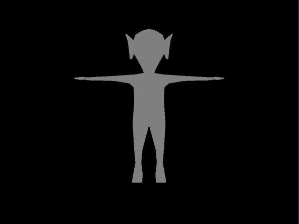
Grayscaling is, like it sounds, the process of removing color from the scene and making it appear completely in grayscale. This is a very simple process, and it is achieved in the fragment shader by outputting a weighted average of the colors, called the luminance. The code looks like this:

#version 420

in vec2 texCoord; // Note that this must be the exact same name as the variable outputted in the vertex shader.

out vec4 color;

uniform sampler2D tex; // The view of the scene, bound as a 2D texture.

void main()
{
	// Sample the scene image at the provided texture coordinates.
	vec4 source = texture(tex, texCoord); 

	// Mix the red, green, and blue channels to get the luminance.
	// The weights used represent the 'optimal' levels of each channel for the human eye.
	float luminance = 0.2989 * source.r + 0.587 * source.g + 0.114 * source.b; 

	// Output the luminance for each color channel, producing gray.
	color = vec4(luminance, luminance, luminance, 1.0f);
}

I’m not going to show the code for it, but for the following code I’m going to assume you have created a shader object called grayscaleShader using the above vertex and fragment shaders, and created and initialized a frame buffer object called mainBuffer (in C++). The following code can then be added to our draw method:

void draw()
{
	// ... clear buffers and any other pre-draw operations here.

	mainBuffer.bind(); // Causes the mainBuffer to be drawn to instead of the back-buffer.
 	// Draw your scene as usual here.
	mainBuffer.unbind();

	grayscaleShader.bind(); // Bind the shader object.
	glBindTexture(GL_TEXTURE_2D, mainBuffer.getColorHandle(0)); // Binds the scene (stored in mainBuffer) as a texture for our grayscale shader.
	drawFullScreenQuad();
	glBindTexture(GL_TEXTURE_2D, GL_NONE);
	grayscaleShader.unbind();
}

Note that since we do not have a frame buffer bound when drawFullScreenQuad is called, it will be drawn to the back-buffer. We could change it so that it is drawn to another frame buffer, which can then be used again for other processing.

Blur

The next effect I will cover this week is blur. Blur is the process of averaging pixels with their neighbors, using weights according to the distance from the original pixel. So, for example, when blurring a given pixel, it will have a certain weight while its direct neighbor will have a slightly less weight. The pixel on the other side of the neighbor will have an even less weight, and so on. The important thing to remember about this is that the weights, when added together, should equal 1. Otherwise, the brightness of the final image will not be the same as the original image. While this process could be done in one shot two-dimensionally, it is a bit easier to instead to it twice, once horizontally and once vertically. Here is the fragment shader code for the horizontal blur:

#version 420

uniform sampler2D uTex; // Source image
uniform float uPixelSize; // Equal to (1.0 / windowWidth)

in vec2 texCoord;

out vec3 outColor;

void main()
{
	// Sample pixels in a horizontal row.
	// The weights add up to 1.
	outColor = vec3(0.0, 0.0, 0.0);

	outColor += 0.06 * texture(uTex, vec2(texCoord.x - 4.0 * uPixelSize, texCoord.y)).rgb;
	outColor += 0.09 * texture(uTex, vec2(texCoord.x - 3.0 * uPixelSize, texCoord.y)).rgb;
	outColor += 0.12 * texture(uTex, vec2(texCoord.x - 2.0 * uPixelSize, texCoord.y)).rgb;
	outColor += 0.15 * texture(uTex, vec2(texCoord.x - uPixelSize, texCoord.y)).rgb;
	outColor += 0.16 * texture(uTex, vec2(texCoord.x, texCoord.y)).rgb;
	outColor += 0.15 * texture(uTex, vec2(texCoord.x + uPixelSize, texCoord.y)).rgb;
	outColor += 0.12 * texture(uTex, vec2(texCoord.x + 2.0 * uPixelSize, texCoord.y)).rgb;
	outColor += 0.09 * texture(uTex, vec2(texCoord.x + 3.0 * uPixelSize, texCoord.y)).rgb;
	outColor += 0.06 * texture(uTex, vec2(texCoord.x + 4.0 * uPixelSize, texCoord.y)).rgb;
}

The shader for the vertical blur is similar, except that we manipulate texCoord.y instead of texCoord.x as above. On the C++ side of things, there are a couple of things that we need for this operation to work. We have to create the shader objects (remember, you need two, one for horizontal and one for vertical), along with three frame buffer objects, the mainBuffer and two extra buffers to apply the blur. When you initialize the color attachment for them, it will look something like:

// extraBuffer1.initColorAttachment(index, width, height, format, filter, wrap);
extraBuffer1.initColorAttachment(0, windowWidth, windowHeight, GL_RGB8, GL_LINEAR, GL_CLAMP_TO_EDGE);
// Note that we are using GL_RGB8 for the format, rather than GL_RGBA8, since we do not care about the alpha channel when blurring.

The two extra frame buffers also don’t need a depth attachment, so we can omit that when initializing them. Once we have all our buffers initialized, we can use the following algorithm to apply the blur to our scene:

void draw()
{
	// ... clear buffers and any other pre-draw operations here.

	mainBuffer.bind(); // Causes the mainBuffer to be drawn to instead of the back-buffer.
 	// Draw your scene as usual here.
	mainBuffer.unbind();

	// First-pass of blur to move data into the two extra buffers.
	// Horizontal blur
	blurHorizontalShader.bind(); // Bind the horizontal blur shader.
	glUniform1f(blurHorizontalShader.pixelSizeLoc, 1.0f / windowWidth); // Send the pixelSize uniform to the shader.
	extraBuffer2.bind(); // Draw to extraBuffer2.
	glBindTexture(GL_TEXTURE_2D, mainBuffer.getColorHandle(0)); // Bind scene texture from mainBuffer.
	drawFullScreenQuad();
	glBindTexture(GL_TEXTURE_2D, GL_NONE);
	extraBuffer2.unbind();
	blurHorizontalShader.unbind();

	// Vertical blur
	blurVerticalShader.bind(); // Bind the vertical blur shader.
	glUniform1f(blurVerticalShader.pixelSizeLoc, 1.0f / windowHeight);
	extraBuffer1.bind(); // Draw to extraBuffer1.
	glBindTexture(GL_TEXTURE_2D, extraBuffer2.getColorHandle(0)); // Bind the horizontally blurred scene texture from extraBuffer2.
	drawFullScreenQuad();
	glBindTexture(GL_TEXTURE_2D, GL_NONE);
	extraBuffer1.unbind();
	blurVerticalShader.unbind();

	// Here, BLOOM_BLUR_PASSES is the number of additional blurring passes that you want to apply.
	// Each pass will make the scene look more and more blurry.
	for (int i = 0; i < BLOOM_BLUR_PASSES; i++)
	{
		// Horizontal
		blurHorizontalShader.bind();
		glUniform1f(blurHorizontalShader.pixelSizeLoc, 1.0f / window->getSize().x);
		extraBuffer2.bind();
		glBindTexture(GL_TEXTURE_2D, extraBuffer1.getColorHandle(0));
		drawFullScreenQuad();
		glBindTexture(GL_TEXTURE_2D, GL_NONE);
		extraBuffer2.unbind();
		blurHorizontalShader.unbind();

		// Vertical
		blurVerticalShader.bind();
		glUniform1f(blurVerticalShader.pixelSizeLoc, 1.0f / window->getSize().y);
		extraBuffer1.bind();
		glBindTexture(GL_TEXTURE_2D, extraBuffer2.getColorHandle(0));
		drawFullScreenQuad();
		glBindTexture(GL_TEXTURE_2D, GL_NONE);
		extraBuffer1.unbind();
		blurVerticalShader.unbind();
	}

	// The last thing we need to do is move the final image from extraBuffer1 to the back-buffer.
	extraBuffer1.moveToBackBuffer(windowWidth, windowHeight);
}

If you only want to use one blur pass, you can remove the for loop, but having it in there is a nice option in case you need a strong blur. Now, what if you wanted to blur the scene and then grayscale it, or vice-versa? Thankfully it’s pretty easy, all you have to do is use the output buffer from one as the input buffer to the other, like so:

// Blur algorithm here, but instead of calling extraBuffer1.moveToBackBuffer(windowWidth, windowHeight)
// we leave the image inside of extraBuffer1.

grayscaleShader.bind(); // Bind the shader object.
glBindTexture(GL_TEXTURE_2D, extraBuffer1.getColorHandle(0)); // Binds the blurred scene (stored in extraBuffer1) as a texture for our grayscale shader.
drawFullScreenQuad();
glBindTexture(GL_TEXTURE_2D, GL_NONE);
grayscaleShader.unbind();

And that’s it. Next week I’m going to talk about another interesting full-screen effect called bloom, and how to implement it.

Intermediate Computer Graphics Week 4: Post-Processing and the Frame Buffer

Post-processing in 3D graphics is a very important concept, because it allows us to add interesting effects with little overhead. It also allows us to use effects that require information from the entirety of the current view. The basic idea of post-processing is that, instead of rendering directly to the display’s back buffer, we first render to a frame buffer in video memory, apply some processing algorithm to that frame buffer, and then render the resulting image to the display. Some examples of post-processing effects are blur, bloom, and toon- or cel-shading.

An (overemphasized) example of bloom.

An (overemphasized) example of bloom.

But first, what is the back buffer, and why do we use it? When rendering an image to the display, it is first stored in a special buffer called the back buffer. When we are ready for the user to see the image, we tell the GPU to switch the back buffer and the display buffer, thus displaying on-screen what was stored in the back buffer. This happens to avoid what is known as screen tearing, where the screen refreshes right in the middle of our drawing attempt. This would cause part of the last frame to be displayed along with part of the current frame, causing a strange disjoint in the image. By drawing to a back buffer, we ensure that the entirety of the image will be drawn to screen when the buffers are switched.

An example of screen tearing.

An example of screen tearing.

So why do we care about the back buffer? Basically, the back buffer is the final buffer that we render to when we want to display something on-screen. If we want to process the image first, we have to use a different buffer to store it. This is where custom frame buffers come in. Frame buffers are objects that can hold both depth and color information, called ‘attachments’, which are basically just textures stored in video memory. In fact, they can hold up to 16 color attachments and 1 depth attachment. Note that you do not have to use both types! A frame buffer can store only color information, only depth information, or both. We can use OpenGL to create frame buffers using the glGenFramebuffers method. This takes two arguments, the number of frame buffers to generate, and an int to store the ID of the created frame buffer. We then initialize the depth attachment and/or the desired number of color attachments using a variety of functions, as shown below.

 // The following code creates a frame buffer, and initializes one depth buffer and two color buffers.
unsigned int WIDTH = 1024, HEIGHT = 768;	// The width and height (in pixels) that you want the frame buffer to be.
unsigned int numColorAttachments = 2;	// We can increase this up to 16

// Generate the frame buffer (fbo stands for frame buffer object).
GLuint fbo;
glGenFramebuffers(1, &fbo);

// buffs is required as a parameter for glDrawBuffers(), which is used when we bind the frame buffer.
GLenum *buffs = new GLenum[numColorAttachments];
for(int i = 0; i < numColorAttachments; i++)
{
	buffs[i] = GL_COLOR_ATTACHMENT0 + i;
}

// Bind the newly created frame buffer, which we need to do to create its attachments.
glBindFrameBuffer(GL_FRAMEBUFFER, fbo);

// Create and initialize the depth attachment.
GLuint depthAttachment = GL_NONE;
glGenTextures(1, &depthAttachment);
glBindTexture(GL_TEXTURE_2D, depthAttachment);
glTexStorage2D(GL_TEXTURE_2D, 1, GL_DEPTH_COMPONENT24, WIDTH, HEIGHT);
glTexParameteri(GL_TEXTURE_2D, GL_TEXTURE_MIN_FILTER, GL_NEAREST);
glTexParameteri(GL_TEXTURE_2D, GL_TEXTURE_MAG_FILTER, GL_NEAREST);
glTexParameteri(GL_TEXTURE_2D, GL_TEXTURE_WRAP_S, GL_CLAMP_TO_EDGE);
glTexParameteri(GL_TEXTURE_2D, GL_TEXTURE_WRAP_T, GL_CLAMP_TO_EDGE);

// Bind the depth attachment to the frame buffer.
glFramebufferTexture2D(GL_FRAMEBUFFER, GL_DEPTH_ATTACHMENT, GL_TEXTURE_2D, depthAttachment, 0);

// Create and initialize the color attachments.
GLuint *colorAttachments = new GLuint[numColorAttachments];

// Note these are just sample options. You can change these to whichever options that you need.
// They don't need to be the same for all color attachments, either. You just have to change the structure of this code to not use a for-loop.
GLint format = GL_RGBA8;
GLint filter = GL_LINEAR;
GLint wrap = GL_CLAMP_TO_EDGE;
for(int i = 0; i < numColorAttachments; i++)
{
	glGenTextures(1, &colorAttachments[i]);
	glBindTexture(GL_TEXTURE_2D, colorAttachments[i]);
	glTexStorage2D(GL_TEXTURE_2D, 1, format, WIDTH, HEIGHT);
	glTexParameteri(GL_TEXTURE_2D, GL_TEXTURE_MIN_FILTER, filter);
	glTexParameteri(GL_TEXTURE_2D, GL_TEXTURE_MAG_FILTER, filter);
	glTexParameteri(GL_TEXTURE_2D, GL_TEXTURE_WRAP_S, wrap);
	glTexParameteri(GL_TEXTURE_2D, GL_TEXTURE_WRAP_T, wrap);

	// Bind the color attachment to the frame buffer.
	glFramebufferTexture2D(GL_FRAMEBUFFER, GL_COLOR_ATTACHMENT0 + i, GL_TEXTURE_2D, colorAttachments[i], 0);
}

// Check the frame buffer to make sure it's valid.
if(glCheckFramebufferStatus(GL_FRAMEBUFFER) != GL_FRAMEBUFFER_COMPLETE)
{
	// Here you could put whatever error-handling code you want, such as a print statement followed by an exit statement.
}

// Unbind the frame buffer until we need it again.
glBindFramebuffer(GL_FRAMEBUFFER, GL_NONE);

Obviously, all of the code shown here could be (and should be!) encapsulated in a custom frame buffer class, but I’ll leave that to the reader to implement. After the frame buffer and its attachments have been created and initialized, we can bind the frame buffer for drawing. However, we should first clear the frame buffer at the beginning of the game loop so that strange things don’t happen when we try to draw to it:

// Clear the frame buffer (and all attachments).
// Uses a bit-wise OR operation to include the appropriate buffers for clearing.
GLbitfield temp = 0;

if (depthAttachment != GL_NONE)
{
	temp = temp | GL_DEPTH_BUFFER_BIT;
}

if (colorAttachments != nullptr)
{
	temp = temp | GL_COLOR_BUFFER_BIT;
}

glBindFramebuffer(GL_FRAMEBUFFER, fbo);
glClear(temp);
glBindFramebuffer(GL_FRAMEBUFFER, GL_NONE);

We then bind the frame buffer for drawing by using the following code:

// Bind the frame buffer for drawing.
glBindFramebuffer(GL_FRAMEBUFFER, fbo);
glDrawBuffers(numColorAttachments, buffs);

And the following code would be used to unbind the frame buffer after drawing is complete:

// Unbind the frame buffer.
glBindFramebuffer(GL_FRAMEBUFFER, GL_NONE);

Now that we have drawn to our frame buffer, in order to see it on screen we must move it to the back-buffer. We can do so by using the following code:

// Move data to the back-buffer.
glBindFramebuffer(GL_READ_FRAMEBUFFER, fbo);	// Our frame buffer is being read from...
glBindFramebuffer(GL_DRAW_FRAMEBUFFER, GL_NONE);// ... and since no buffer is specified to draw to, the back-buffer is automatically used.

// Function provided by OpenGL to draw from one buffer to another. How convenient!
glBlitFramebuffer(0, 0, WIDTH, HEIGHT, 0, 0, WIDTH, HEIGHT, GL_COLOR_BUFFER_BIT, GL_NEAREST);

glBindFramebuffer(GL_FRAMEBUFFER, GL_NONE);

When we are completely done with the frame buffer, we should dispose of it properly using the following code:

if (buffs != nullptr)
{
	delete[] buffs;
	buffs = nullptr;
}

if (colorAttachments != nullptr)
{
	for (int i = 0; i < numColorAttachments; i++)
	{
		glDeleteTextures(1, &colorAttachments[i]);
	}

	delete[] colorAttachments;
	colorAttachments = nullptr;
}

if (depthAttachment != GL_NONE)
{
	glDeleteTextures(1, &depthAttachment);
	depthAttachment = GL_NONE;
}

numColorAttachments = 0;

glDeleteFramebuffers(1, &fbo);
fbo = GL_NONE;

This has become a bit of a long post, so we’ll leave it at that for now. Next week, I’ll talk about some basic post-processing shaders, and show you how to use them alongside your frame buffer to produce some interesting effects. Make sure to convert the code shown today into a C++ class, because next week I will be referencing function calls instead of the above code.

Intermediate Computer Graphics Week 3: Lighting

The lighting in a scene is very important. Not only does it set the mood for the scene, but it also affects how realistic the scene looks. There are three main categories of lighting: emissive, direct, and indirect. I won’t describe indirect lighting in detail, but it is the light that hits a point in the scene after bouncing off other surfaces in the scene. To calculate the brightness of a particular point in a scene, you just add up the emissive, direct, and indirect lights that affect that particular point: Brightness_{Point} = L_{Emissive} + L_{Direct} + L_{Indirect}

Emissive lighting is the light that is emitted by a particular point in the scene. The value of the emissive light can be calculated by multiplying the intensity of the light by the color of the light: L_{Emissive} = I_{Emissive} * \overrightarrow{Color}_{[RGB]}

Direct lighting is the light that directly hits the point from another light source. There are three components of direct lighting: ambient, diffuse, and specular, which are added together to get the direct lighting: L_{Direct} = L_{Ambient} + L_{Diffuse} + L_{Specular}

lighting-specular-sphere

Ambient lighting is a simplification we use to approximate the ambient light in a room. Similar to the formula for emissive light, ambient light can be calculated by multiplying the intensity of the light by the ambient color: L_{Ambient} = I * \overrightarrow{Color}_{[RGB]}

Diffuse light is light that is reflected off a surface at many angles. A surface with a high diffuse component (and low specular component) looks matte. It depends on the angle of the light source with respect to the normal of the surface, and also factors in attenuation. The following formula is used to calculate the diffuse component:

L_{Diffuse} = \frac{k * I * (\overrightarrow{L} \cdot \overrightarrow{N})}{c_1 + c_2*d} * \overrightarrow{Color}_{[RGB]}

where k is a constant that we can manipulate, I is the intensity of the light source, \overrightarrow{L} is the vector from the surface point to the light source, \overrightarrow{N} is the normal vector of the surface point, c_1 and c_2 are manipulable attenuation parameters, and d is the distance from the surface point to the light source.

Lambert2

Specular light is light that is reflected off a surface at a particular angle. A surface with a high specular component will appear shiny. This component, like diffuse, depends on the angle of the light source with respect to the surface normal, but it also depends on the direction of the viewer. The following formula is used to calculate the specular component:

L_{Specular} = k * I * (\overrightarrow{R} \cdot \overrightarrow{V})^n * \overrightarrow{Color}_{[RGB]}

where k is a constant that we can manipulate, I is the intensity of the light source, \overrightarrow{R} is a vector representing the reflected light vector, \overrightarrow{V} is the vector from the surface point to the viewer, and n is called the specular reflection exponent, which can be manipulated to alter the look of the specular reflection. When n is 1, it gives a smooth falloff, and when it is larger it gives a more focused reflection.

specular_light

Intermediate Computer Graphics Week 2: Shaders

This week, I’m going to go into a little more detail about the vertex and fragment shaders, as well as give a few examples of each.

As I discussed last week, the vertex and fragment shaders are steps in the graphics pipeline. The vertex shader takes raw vertex data from our games and outputs the vertices in screen space, along with any other data that is needed in later steps. The fragment shader takes fragments from the rasterizer, applies any texture mapping, lighting, and other effects, and outputs the final colour value for each pixel.

Here is a very basic version of the vertex shader:

#version 420

layout (location = 0) in vec3 position;
layout (location = 1) in vec2 uv;
layout (location = 2) in vec3 normal;

uniform mat4 model;
uniform mat4 view;
uniform mat4 projection;

void main()
{
     gl_Position = projection * view * model * vec4(position, 1.0f);
}

All that this shader does is take the vertex data from our game and converts the position to clip space. The very first line just specifies what version of OpenGL we are using. The next three lines define the input that we are getting from the vertex array from our game. Specifying “layout (location = x)” ensures that the data will arrive at our shader in the required order. Therefore, the vertex array being passed in from our game should look like {x1, y1, z1, u1, v1, nx1, ny1, nz1, x2, y2, z2, …}, where x, y, and z are the coordinates of the vertex, u and v are the texture coordinates mapped to the vertex, and nx, ny, and nz are the components of the normal vector for the vertex. The number after each indicates the number of the current vertex. Note that vertices will be ordered in the array according to the faces of the geometry being displayed. For example, the first three vertices will form the first face in the model, and the order in which they occur indicate the direction of the face. So, if the vertices appear in counter-clockwise order on screen, they will be front-facing, and vice-versa. This is called the “winding order”. An important thing to notice however is that the above data is coming in to the shader one vertex at a time, so we do not need to worry about winding order right now.

Image depicting the winding order of faces on a cube. Since the vertices on the face to the right occur in counter-clockwise order, they are front-facing with respect to the viewer. The face on the left, however, has its vertices occurring in clockwise-order, and thus is facing away from the viewer.

The next three lines are called uniforms, and they are data that is constant for all of the vertices in the vertex array. In this shader, they are the model matrix, the view matrix, and the projection matrix. The model matrix represents the transform from the original model created in Maya (or whatever other 3D modelling program that is used) to its position in our game world. The view matrix transforms that position so that the viewer is at the origin of the scene, and everything else is relative to it. The projection matrix represents the “lens” of our camera, and is used to define how the 3D world in our game should be “projected” onto our 2D screen. All of these uniforms must be calculated and kept track of in the game.

Finally, the only line we have in our main() method just multiplies the vertex position with the model, view, and projection matrix. Note that our vertex position is stored in a three-dimensional vector, and so in order to multiply it with the four-dimensional matrices, we must first convert it to a four-dimensional vector using the function vec4(). The gl_Position variable is a special one provided by OpenGL, and it is how we output the position of the vertex in clip space.

Here is a very basic version of the fragment shader:

#version 420

out vec4 color;

void main()
{
     color = vec4(0.5f, 0.5f, 0.5f, 1.0f);
}

This shader simply outputs gray for the color of the entire model that is displayed on screen. This is achieved via the output variable “color”. Note that if you run the game with this shader, you will only get a silhouette of the model, but you wont be able to see any definition. This is due to the fact that there is no lighting, and therefore no shading of the model.

Here's what a model would look like using the above basic shaders. We only see a silhouette, and no definition.

Here’s what a model would look like using the above basic shaders. We only see a silhouette, and no definition.


Now we can go a bit further to create a more advanced set of shaders. The following shaders are capable of texture mapping the passed in vertices to a given texture, along with applying some simple lighting calculations. The vertex shader is as follows:

#version 420

layout (location = 0) in vec3 position;
layout (location = 1) in vec2 uv;
layout (location = 2) in vec3 normal;

out vec3 Position;
out vec2 UV;
out vec3 Normal;

uniform mat4 model;
uniform mat4 view;
uniform mat4 projection;

void main()
{
     gl_Position = projection * view * model * vec4(position, 1.0f);
     Position = vec3(model * vec4(position, 1.0f));
     UV = uv;
     Normal = mat3(transpose(inverse(model))) * normal;
}

This does basically the same thing as our original vertex shader, except that it also passes along some information to the fragment shader. These are specified in the list of output variables declared underneath the input variables. The fragment shader does its calculations in world space coordinates, however, so we must convert the Position and Normal vectors to world space, rather than just passing the model space inputs. This is easy for the position, we just multiply it by the model transform matrix. For the normal vector, however, it is a little more complicated, due to the fact that the normal is just a direction and not a position in space. I wont go into the details, but just know that you have to multiply the normal by the transpose of the inverse of the model transform matrix. If you want to read up on why this is the case, you can check out this article.

Next is the fragment shader:

#version 420

in vec3 Position;
in vec2 UV;
in vec3 Normal;

out vec4 color;

uniform vec4 objectColor;
uniform vec3 lightPos;
uniform vec3 viewPos;
uniform sampler2D tex;

void main()
{
 vec3 ambientComponent = vec3(0.5f);
 vec3 diffuseComponent = vec3(0.5f);
 vec3 specularComponent = vec3(0.2f);

 vec3 norm = normalize(Normal);
 vec3 lightDir = normalize(lightPos - Position);

 float diffuse = max(dot(norm, lightDir), 0.0);
 diffuseComponent = diffuse * diffuseComponent;

 vec3 viewDir = normalize(viewPos - Position);
 vec3 reflectDir = reflect(-lightDir, norm);

 float specular = pow(max(dot(viewDir, reflectDir), 0.0), 32);
 specularComponent = specular * specularComponent;

 vec3 result = (ambientComponent + diffuseComponent + specularComponent);
 color = vec4(result, 1.0f) * texture(tex, UV) * objectColor;
}

Now things are starting to get interesting. This shader is capable of lighting calculations for a single light in the scene, producing some interesting visuals based on the values you use for the ambient, diffuse, and specular components. Obviously with this shader, these components are constant for every object in the scene, but they could be instead converted to a uniform so that they could be changed for each object. They could even be vertex-based instead, if you really wanted to. But let’s get right into dissecting the code in this shader.

The first addition we are making to this shader is the declaration of the input variables at the beginning of the code. Note that these variables must exactly match the output variables from the vertex shader, including upper / lower case letters. After the output variable, we also added four uniforms. The first one is an optional color that we can use to tint the overall color of the model. Using white for this value will make the object look like it normally would. The second uniform is the position of the light in the scene. The third is the position of the camera in the scene. The last uniform is the reference to the texture that will be applied to this model, which must be bound in our game before the shader is called.

Next week, I will go into more detail regarding lighting and lighting calculations, but for now just know that we are calculating the lighting on the model using three values: the normal vector of the surface being lit, the position of the light in the scene, and the position of the viewer (i.e. the camera) in the scene. It is these calculations that comprise lines 16-32 of the shader. The last line simply combines everything together. By multiplying the result of the lighting calculations with the mapped texture (obtained by using OpenGL’s built-in texture() function), and subsequently multiplying by the optional color tint, we can obtain interesting lighting of our models.

Here's what our model looks like using our new set of shaders. Not bad!

Here’s what our model looks like using our new set of shaders. Not bad!

Intermediate Computer Graphics Week 1: The Graphics Pipeline

In order to be able to create interesting graphical effects for our games, we must first understand the underlying process that OpenGL uses to transform the data in our games to pixels on the screen. This process is called the “graphics pipeline” or “rendering pipeline”. There are several steps that are involved in this pipeline, some which we are able to manipulate and some we cannot. In addition, some of the steps are optional and may be skipped unless we choose to use them. The following image shows all of the steps in the graphics pipeline. The blue boxes are steps that we can manipulate via programming, and the ones with dashed outlines are optional steps.

The steps involved in the graphics pipeline. Blue boxes represent steps that are programmable, whereas yellow ones are not. Boxes that have a dotted outline are optional steps.

The first step is the vertex shader. This is a program that we write to process vertex attribute data, such as position, on the GPU. It does this on a per-vertex basis, thus only processing a single vertex at a time. The main purpose of the vertex shader is to convert vertex positions from world-space to screen-space, and to pass the resulting information to subsequent steps in the pipeline. I will discuss vertex shaders more in-depth in next week’s post on shaders.

The next group of steps concern tessellation, which is the process of subdividing patches of vertex data into smaller primitives. I wont go into much detail on these here, but important things to know about them is that they are optional, but that we can manipulate them if we need to.

The next step is the geometry shader. This is another optional shader that we are able to program if we need to. It is capable of creating new geometry on-the-fly using primitives (which were created during primitive assembly after the vertex shader) as input. This essentially allows us to transfer workload from the CPU to the GPU by letting it generate complex geometry from relatively simple input data.

The clipping step is a non-programmable step where any primitives that lie on the edge of the screen are subdivided into smaller primitives that are either completely within or outside of the screen. Subsequently, face culling takes place, where any faces that are outside of the viewing region or are hidden behind other faces are removed.

Rasterization is the process of converting primitives to sequences of fragments. Fragments contain all of the data, on a per-pixel basis, that the fragment shader needs in order to display them on-screen. This can include position, normal, and texture mapping data. Rasterization is not a programmable step of the graphics pipeline.

A graphical representation of several steps in the graphics pipeline.

The fragment shader is the last programmable step in the graphics pipeline. It operates on a per-pixel basis, taking fragments as input, which include all of the data specified above, and outputting the final color of the current pixel. Many operations can take place in the fragment shader, such as texture mapping and lighting calculations. I will go further into depth on fragment shaders in next week’s post on shaders.

The final step in the graphics pipeline is a series of tests and blending operations. The tests are used to cull any fragments that should not be added to the framebuffer for whatever reason. Blending is then used to blend fragments with any already existing in the framebuffer. Finally, the resulting data is written to the framebuffer.