This week, I’m going to go into a little more detail about the vertex and fragment shaders, as well as give a few examples of each.
As I discussed last week, the vertex and fragment shaders are steps in the graphics pipeline. The vertex shader takes raw vertex data from our games and outputs the vertices in screen space, along with any other data that is needed in later steps. The fragment shader takes fragments from the rasterizer, applies any texture mapping, lighting, and other effects, and outputs the final colour value for each pixel.
Here is a very basic version of the vertex shader:
#version 420

layout (location = 0) in vec3 position;
layout (location = 1) in vec2 uv;
layout (location = 2) in vec3 normal;

uniform mat4 model;
uniform mat4 view;
uniform mat4 projection;

void main()
{
     gl_Position = projection * view * model * vec4(position, 1.0f);
}
All that this shader does is take the vertex data from our game and converts the position to clip space. The very first line just specifies what version of OpenGL we are using. The next three lines define the input that we are getting from the vertex array from our game. Specifying “layout (location = x)” ensures that the data will arrive at our shader in the required order. Therefore, the vertex array being passed in from our game should look like {x1, y1, z1, u1, v1, nx1, ny1, nz1, x2, y2, z2, …}, where x, y, and z are the coordinates of the vertex, u and v are the texture coordinates mapped to the vertex, and nx, ny, and nz are the components of the normal vector for the vertex. The number after each indicates the number of the current vertex. Note that vertices will be ordered in the array according to the faces of the geometry being displayed. For example, the first three vertices will form the first face in the model, and the order in which they occur indicate the direction of the face. So, if the vertices appear in counter-clockwise order on screen, they will be front-facing, and vice-versa. This is called the “winding order”. An important thing to notice however is that the above data is coming in to the shader one vertex at a time, so we do not need to worry about winding order right now.

Image depicting the winding order of faces on a cube. Since the vertices on the face to the right occur in counter-clockwise order, they are front-facing with respect to the viewer. The face on the left, however, has its vertices occurring in clockwise-order, and thus is facing away from the viewer.
The next three lines are called uniforms, and they are data that is constant for all of the vertices in the vertex array. In this shader, they are the model matrix, the view matrix, and the projection matrix. The model matrix represents the transform from the original model created in Maya (or whatever other 3D modelling program that is used) to its position in our game world. The view matrix transforms that position so that the viewer is at the origin of the scene, and everything else is relative to it. The projection matrix represents the “lens” of our camera, and is used to define how the 3D world in our game should be “projected” onto our 2D screen. All of these uniforms must be calculated and kept track of in the game.
Finally, the only line we have in our main() method just multiplies the vertex position with the model, view, and projection matrix. Note that our vertex position is stored in a three-dimensional vector, and so in order to multiply it with the four-dimensional matrices, we must first convert it to a four-dimensional vector using the function vec4(). The gl_Position variable is a special one provided by OpenGL, and it is how we output the position of the vertex in clip space.
Here is a very basic version of the fragment shader:
#version 420

out vec4 color;

void main()
{
     color = vec4(0.5f, 0.5f, 0.5f, 1.0f);
}
This shader simply outputs gray for the color of the entire model that is displayed on screen. This is achieved via the output variable “color”. Note that if you run the game with this shader, you will only get a silhouette of the model, but you wont be able to see any definition. This is due to the fact that there is no lighting, and therefore no shading of the model.

Here’s what a model would look like using the above basic shaders. We only see a silhouette, and no definition.
Now we can go a bit further to create a more advanced set of shaders. The following shaders are capable of texture mapping the passed in vertices to a given texture, along with applying some simple lighting calculations. The vertex shader is as follows:
#version 420

layout (location = 0) in vec3 position;
layout (location = 1) in vec2 uv;
layout (location = 2) in vec3 normal;

out vec3 Position;
out vec2 UV;
out vec3 Normal;

uniform mat4 model;
uniform mat4 view;
uniform mat4 projection;

void main()
{
     gl_Position = projection * view * model * vec4(position, 1.0f);
     Position = vec3(model * vec4(position, 1.0f));
     UV = uv;
     Normal = mat3(transpose(inverse(model))) * normal;
}
This does basically the same thing as our original vertex shader, except that it also passes along some information to the fragment shader. These are specified in the list of output variables declared underneath the input variables. The fragment shader does its calculations in world space coordinates, however, so we must convert the Position and Normal vectors to world space, rather than just passing the model space inputs. This is easy for the position, we just multiply it by the model transform matrix. For the normal vector, however, it is a little more complicated, due to the fact that the normal is just a direction and not a position in space. I wont go into the details, but just know that you have to multiply the normal by the transpose of the inverse of the model transform matrix. If you want to read up on why this is the case, you can check out this article.
Next is the fragment shader:
#version 420

in vec3 Position;
in vec2 UV;
in vec3 Normal;

out vec4 color;

uniform vec4 objectColor;
uniform vec3 lightPos;
uniform vec3 viewPos;
uniform sampler2D tex;

void main()
{
 vec3 ambientComponent = vec3(0.5f);
 vec3 diffuseComponent = vec3(0.5f);
 vec3 specularComponent = vec3(0.2f);

 vec3 norm = normalize(Normal);
 vec3 lightDir = normalize(lightPos - Position);

 float diffuse = max(dot(norm, lightDir), 0.0);
 diffuseComponent = diffuse * diffuseComponent;

 vec3 viewDir = normalize(viewPos - Position);
 vec3 reflectDir = reflect(-lightDir, norm);

 float specular = pow(max(dot(viewDir, reflectDir), 0.0), 32);
 specularComponent = specular * specularComponent;

 vec3 result = (ambientComponent + diffuseComponent + specularComponent);
 color = vec4(result, 1.0f) * texture(tex, UV) * objectColor;
}
Now things are starting to get interesting. This shader is capable of lighting calculations for a single light in the scene, producing some interesting visuals based on the values you use for the ambient, diffuse, and specular components. Obviously with this shader, these components are constant for every object in the scene, but they could be instead converted to a uniform so that they could be changed for each object. They could even be vertex-based instead, if you really wanted to. But let’s get right into dissecting the code in this shader.
The first addition we are making to this shader is the declaration of the input variables at the beginning of the code. Note that these variables must exactly match the output variables from the vertex shader, including upper / lower case letters. After the output variable, we also added four uniforms. The first one is an optional color that we can use to tint the overall color of the model. Using white for this value will make the object look like it normally would. The second uniform is the position of the light in the scene. The third is the position of the camera in the scene. The last uniform is the reference to the texture that will be applied to this model, which must be bound in our game before the shader is called.
Next week, I will go into more detail regarding lighting and lighting calculations, but for now just know that we are calculating the lighting on the model using three values: the normal vector of the surface being lit, the position of the light in the scene, and the position of the viewer (i.e. the camera) in the scene. It is these calculations that comprise lines 16-32 of the shader. The last line simply combines everything together. By multiplying the result of the lighting calculations with the mapped texture (obtained by using OpenGL’s built-in texture() function), and subsequently multiplying by the optional color tint, we can obtain interesting lighting of our models.
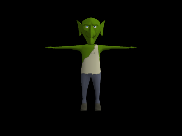
Here’s what our model looks like using our new set of shaders. Not bad!
